We know that motors are generally divided into electric motors and generators. Electric motors are devices that convert electrical energy into mechanical energy. Generators are devices that convert mechanical energy into electrical energy. The operating principle of electric motors is based on Faraday's law of electromagnetic induction. When the motor performs energy conversion, it must have two major components that can move relative to each other:
a component that establishes an excitation magnetic field,
An induced component that induces an electromotive force and flows through the operating current.
Of these two components, the stationary one is called the stator, and the rotating motion is called the rotor. The electromagnetic torque is generated by the interaction of the excitation magnetic field in the air gap with the magnetic field established by the current in the inductive component. By the action of electromagnetic torque, the generator absorbs mechanical power from the mechanical system, and the motor outputs mechanical power to the mechanical system. Different ways of establishing the above two magnetic fields form different types of motors. Today we are talking about DC motors that are commonly used in makers or in technical DIY production or in some conventional projects. They are used to be called DC geared motors or motors.
Internal structure of DC motor

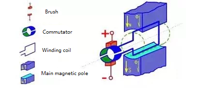
On its fixed portion (stator), a pair of DC-excited stationary main poles N and S are mounted, and an armature core is mounted on the rotating portion (rotor). There is an air gap between the stator and the rotor. An armature coil composed of two conductors A and X is placed on the armature core, and the first end and the end of the coil are respectively connected to two arc-shaped copper pieces, which are called commutating segments. The commutator segments are insulated from each other, and the whole of the commutator segments is called a commutator. The commutator is fixed on the rotating shaft, and the commutator piece and the rotating shaft are also insulated from each other. A pair of fixed brushes B1 and B2 are placed on the commutator segments, and when the armature rotates, the armature coils are connected to the external circuit through the commutator segments and the brushes.
DC motor operating principle
If a single-chip microcomputer is used to control a motor with a rated input voltage of 5V, there is a phenomenon that the two wires of the motor are directly connected to the power supply, the motor moves, and then the two wires are reversed, and the motor will be reversed. Why is this?
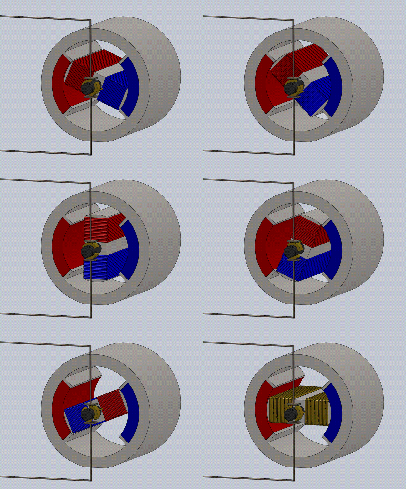
Let us first look at such an animation:

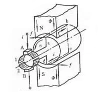
The phenomenon mentioned above is also very well explained. Look at the picture:

If DC power is applied to the two brushes, a direct current flows from the brush A, flows through the coil abcd, and flows out from the brush B. According to the knowledge of electromagnetic induction, the current carrying conductors ab and cd will be subjected to the Ampere force. The direction can be determined by the left-hand rule, and the force received by the two segments of the conductor creates a torque that causes the rotor to rotate counterclockwise. Note that the external power supply is DC, but due to the action of the brush and the commutator, the current flowing through the coil is alternating, and the direction of the torque generated is constant. If the direction of this rotation is defined as the positive direction, then when we reverse the vcc and gnd, the reversal occurs, which is a good explanation. In fact, the direction of the ampere force of the conductor bar is different.
The principle is so much to say here. Thank you for viewing :).
Contact: Foneacc Motor Sales Team
Phone: +86-13923860676
E-mail: sales@foneacc.com
Add: Building A, No. 58 Qiaonan RD, Fuyong Street, Bao An District. Shenzhen, China